v
|
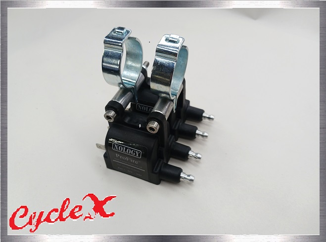
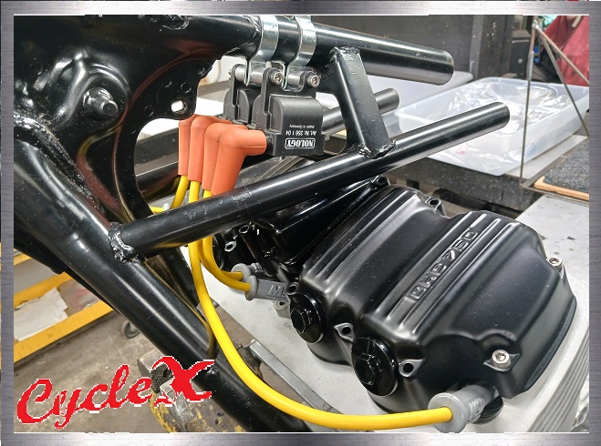
CycleX coils
and mounting brackets.
|
|
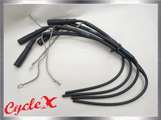
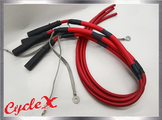
Massive spark.
Nology HotWires Spark Plugs
Wires - YouTube |
|
|
|
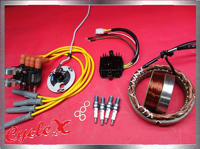
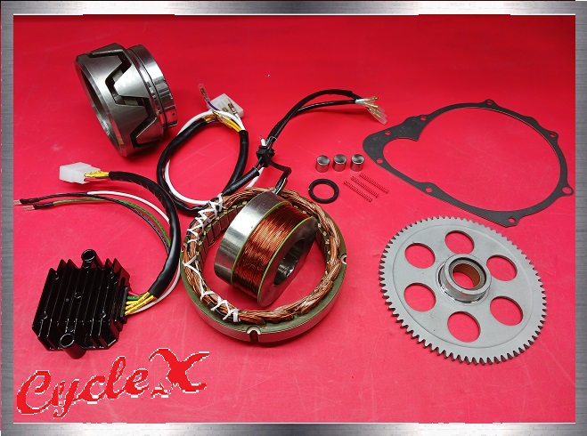
The
ultimate electrical kit!
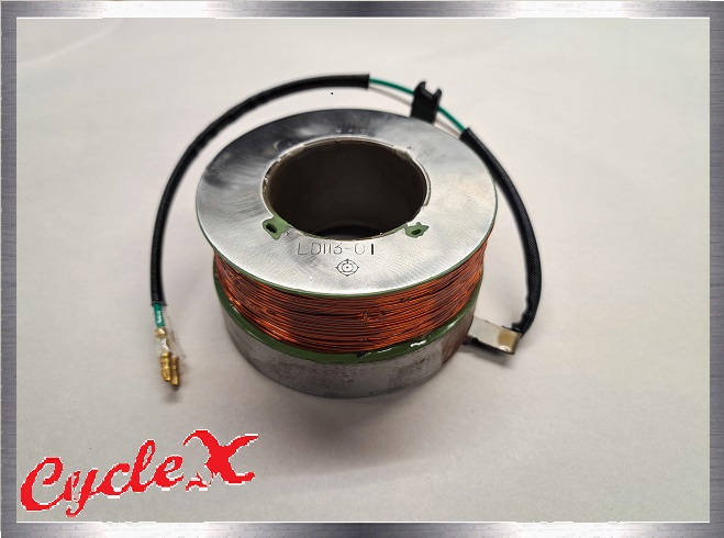
*Reliable and world class quality stator. (USA)
|
|
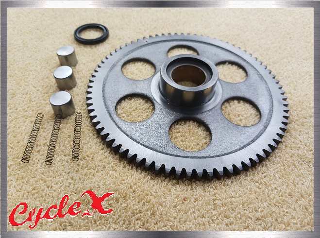
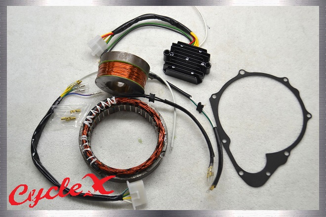
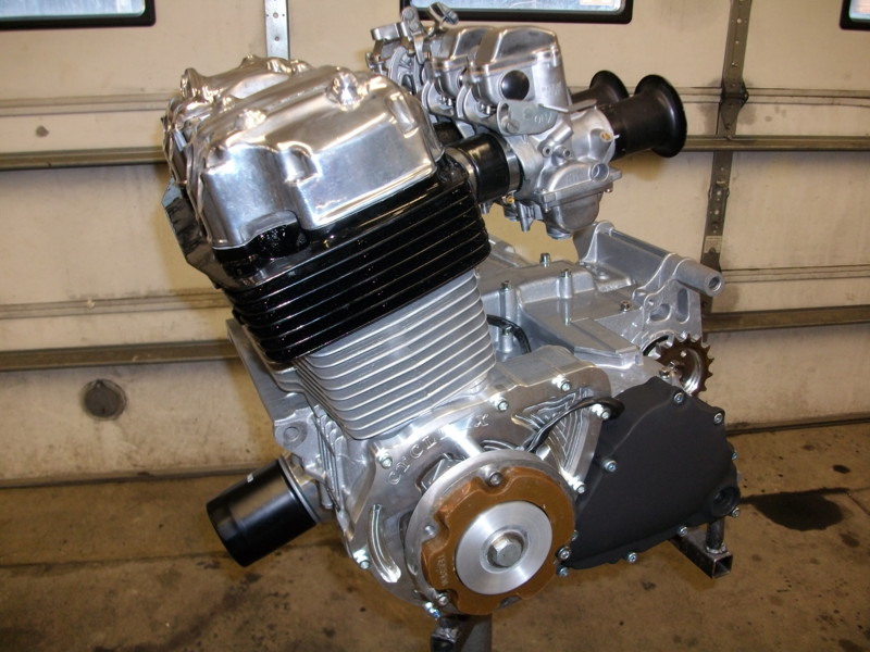
Honda CB750
(69-78) Complete Refurbished Charging
Systems
These refurbished,
rewound stators and field coils should solve your
charging problems for good. Fresh wires and exit rubbers
with make your assembling procedure a breeze. |
|
|
|
|
|
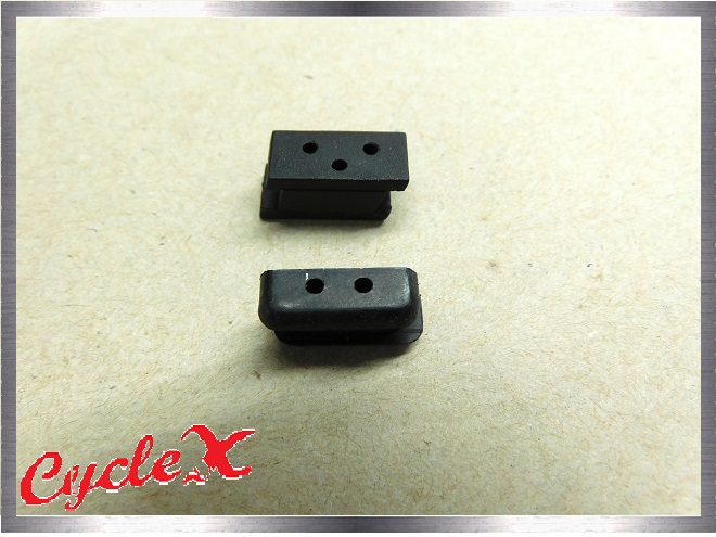
Stator & Field
Coil Wire Exit Rubbers |
|
High Performance 500/550 Field Coils
Remanufactured
alternator, generator field coils for 71-78 Honda cb500 and 550 models. |
|
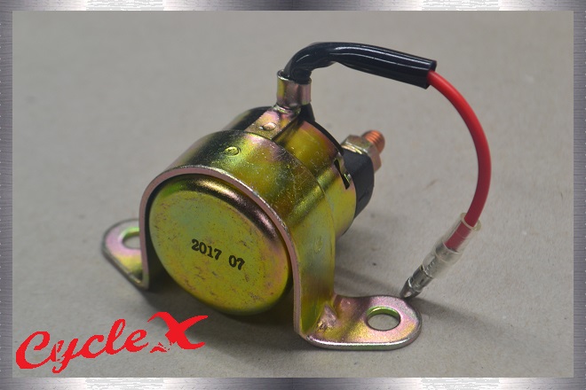
Easy Mount Solenoid A solenoid with a mount tab? That should make things easy. Most starter solenoids require that rubber booty for mounting. Our NEW solenoid has tabs for mounting. $39.95 EL-004 |
|
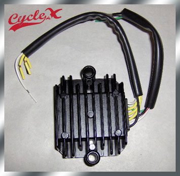
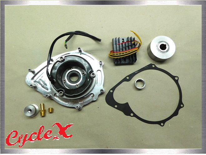
Regulator / Rectifier Replace
your original components with a solid state unit. Mount it where you
would like.
|
|
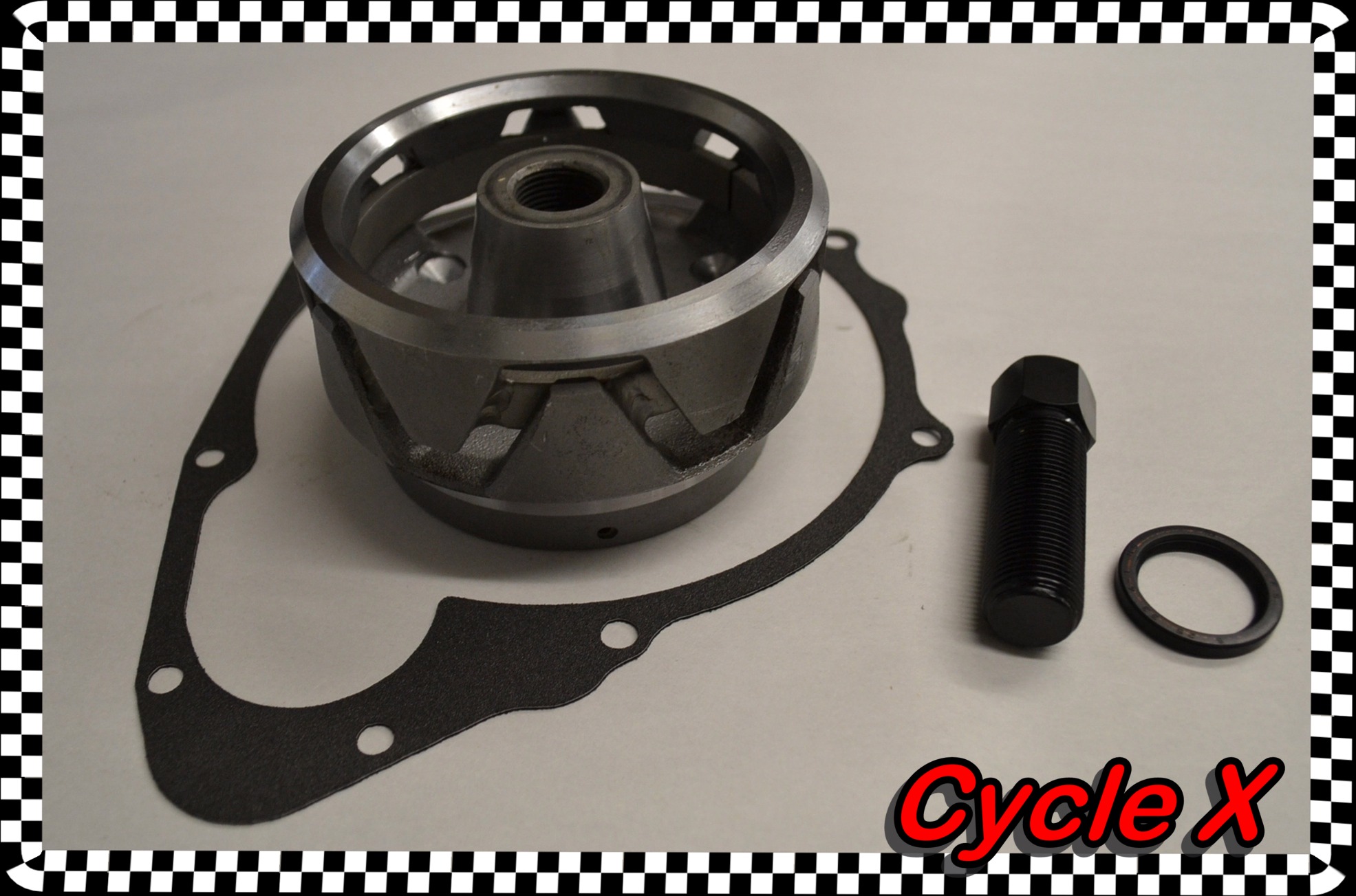
Note: Exchange basis only (Send yours and we'll send you a lightened alternator) ENL-020A $146.95 Call or e-mail to order.
|
|
A 3.99% customer service charge is applied to all phone orders.
If ordering via phone, please also provide the part # of any products you are interested in for faster and more accurate service.
If you encounter a (rare) broken button as you're trying to add parts to your cart (going to PayPal summary instead of your cart or not opening PayPal at all) or anything else of concern, please call us to report it. We'll try to have it fixed for your convenience within the next 5-10 minutes. Afterwards, refresh the page and try again.
NOTE: As of July 1st, 2018, an extended goods and services tax (GST) has been applied to all Australian consumers buying overseas, charging an extra 10% in taxes to us with each purchase. To ensure that you can continue to purchase from us in Australia and we can provide our parts at our usual lower cost, please contact us at the email below if interested in any particular parts so that we can make a special shipping arrangement for you.
It is the sole and
exclusive responsibility of the purchaser to determine the suitability of any
part, product or work for his or her use.
The purchaser shall assume all legal, personal injury risk and liability and all
other obligations, duties and risks therewith.
There is no warranty on High Performance products.
Click to go back to our home page
Cycle X Global Headquarters
6246 US Hwy 51 South
Hazelhurst, WI 54531
Phone: 715-356-7346
Email: hotrodcyclex@gmail.com
.jpg)